Marine LNG supply
Our concept includes a marine LNG supply interface. It would require a compatible jetty, transfer equipment and coordinated ship–shore procedures. We have not confirmed a port concession, vessel contract or terminal approval.
Our concept connects marine LNG supply, storage, road transport and customer facilities. Explore the diagram to understand the equipment and the engineering work needed to bring a project into service.
Supply · Store · Transport · Convert · Deliver
This is our gas-supply concept, subject to detailed engineering. It shows how facilities could connect; it does not represent assets we own or operate, approved projects or committed construction.
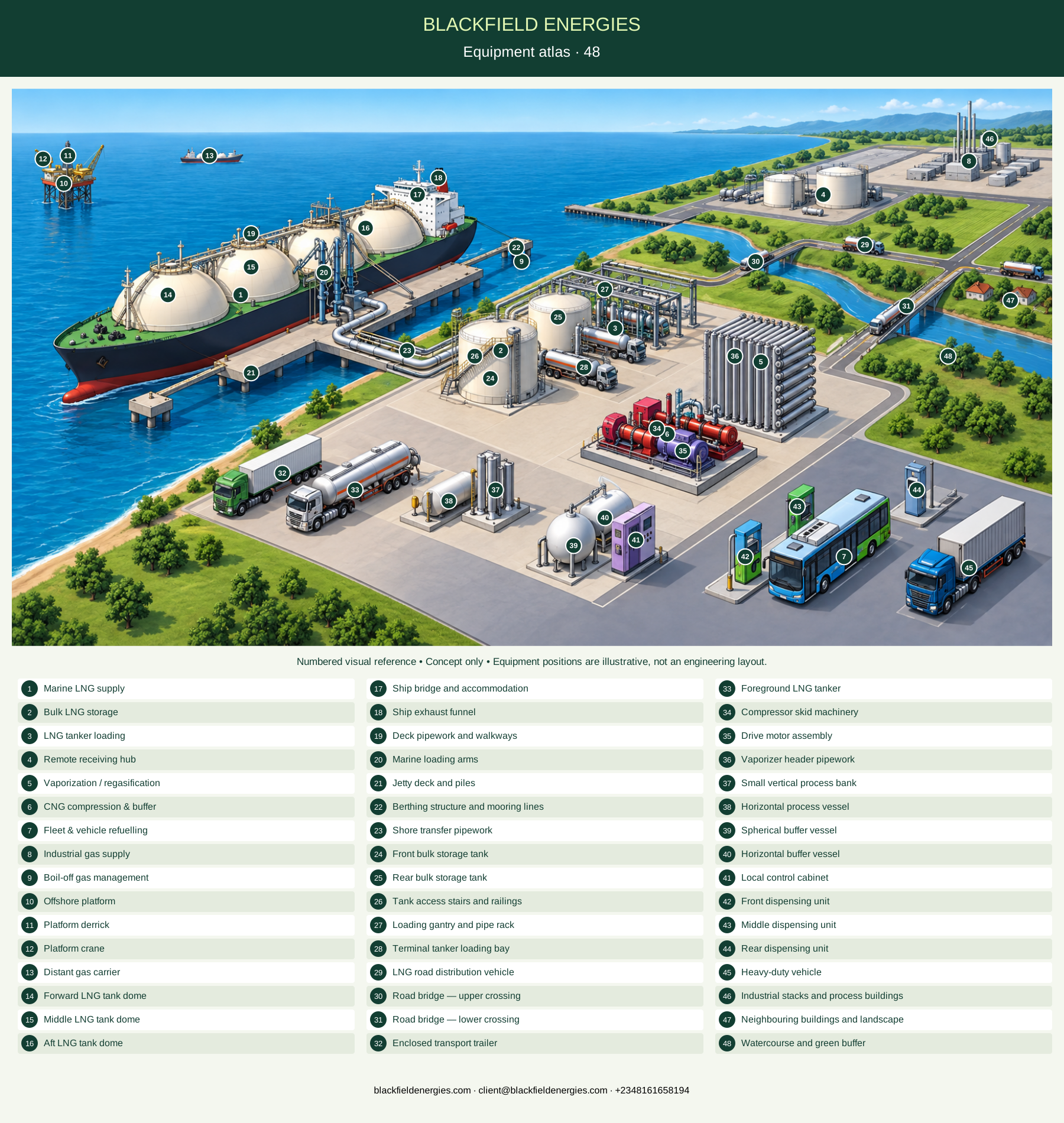
Explore 48 numbered features. Search or filter the register, select a marker for details, or show names on the enlarged diagram. Numbers match the downloadable illustrated key.
Coloured routes explain functional relationships; they are not physical pipe alignments, a piping and instrumentation diagram, or approved operating instructions. Equipment positions and sizes are illustrative.
Our concept includes a marine LNG supply interface. It would require a compatible jetty, transfer equipment and coordinated ship–shore procedures. We have not confirmed a port concession, vessel contract or terminal approval.
Coloured routes explain functional relationships; they are not physical pipe alignments, a piping and instrumentation diagram, or approved operating instructions. Equipment positions and sizes are illustrative.
Our concept includes a marine LNG supply interface. It would require a compatible jetty, transfer equipment and coordinated ship–shore procedures. We have not confirmed a port concession, vessel contract or terminal approval.
Cryogenic storage provides a buffer between deliveries and downstream demand. Tank selection, containment, transfer systems and pressure management require a site-specific design basis; no tank capacity is established by this illustration.
The loading terminal connects bulk storage with road tankers. A virtual pipeline is a transport service, not a physical pipeline: its feasibility depends on loading cycles, travel times, unloading, payload and supply reliability.
We envisage receiving hubs that accept trucked LNG for local storage and use. We would assess unloading, storage autonomy and demand together. The illustrated hub is not a site we have acquired or brought into operation.
Vaporization changes LNG from liquid to gas. It does not by itself establish CNG dispensing pressure. Gas conditions, heat supply, pressure control and downstream equipment must be defined for the selected design.
In the illustrative gas-compression pathway, conditioned gas is compressed and buffered before dispensing. Compressor duty and storage must match inlet conditions and demand. Alternative LNG-to-CNG configurations require their own engineered process definition.
Dispensers connect the station to compatible vehicles. Metering, connectors, vehicle circulation and simultaneous demand must be coordinated with the station equipment. Explore the fleet calculator and station models for the next level of planning.
Regasified natural gas may serve an industrial user through a suitable local distribution connection. Required gas quality, pressure, metering, availability and customer equipment must be confirmed. This branch is distinct from vehicle CNG dispensing.
Functional annotation only: a dedicated boil-off gas recovery package is not separately identifiable in this illustration.
Visible feature in the conceptual illustration. Identification describes its appearance; ratings, duties and installed status are not established.
Visible feature in the conceptual illustration. Identification describes its appearance; ratings, duties and installed status are not established.
Visible feature in the conceptual illustration. Identification describes its appearance; ratings, duties and installed status are not established.
Visible feature in the conceptual illustration. Identification describes its appearance; ratings, duties and installed status are not established.
Visible feature in the conceptual illustration. Identification describes its appearance; ratings, duties and installed status are not established.
Visible feature in the conceptual illustration. Identification describes its appearance; ratings, duties and installed status are not established.
Visible feature in the conceptual illustration. Identification describes its appearance; ratings, duties and installed status are not established.
Visible feature in the conceptual illustration. Identification describes its appearance; ratings, duties and installed status are not established.
Visible feature in the conceptual illustration. Identification describes its appearance; ratings, duties and installed status are not established.
Visible feature in the conceptual illustration. Identification describes its appearance; ratings, duties and installed status are not established.
Visible feature in the conceptual illustration. Identification describes its appearance; ratings, duties and installed status are not established.
Visible feature in the conceptual illustration. Identification describes its appearance; ratings, duties and installed status are not established.
Visible feature in the conceptual illustration. Identification describes its appearance; ratings, duties and installed status are not established.
Visible feature in the conceptual illustration. Identification describes its appearance; ratings, duties and installed status are not established.
Visible feature in the conceptual illustration. Identification describes its appearance; ratings, duties and installed status are not established.
Visible feature in the conceptual illustration. Identification describes its appearance; ratings, duties and installed status are not established.
Visible feature in the conceptual illustration. Identification describes its appearance; ratings, duties and installed status are not established.
Visible feature in the conceptual illustration. Identification describes its appearance; ratings, duties and installed status are not established.
Visible feature in the conceptual illustration. Identification describes its appearance; ratings, duties and installed status are not established.
Visible feature in the conceptual illustration. Identification describes its appearance; ratings, duties and installed status are not established.
Visible feature in the conceptual illustration. Identification describes its appearance; ratings, duties and installed status are not established.
Visible feature in the conceptual illustration. Identification describes its appearance; ratings, duties and installed status are not established.
Visible feature in the conceptual illustration. Identification describes its appearance; ratings, duties and installed status are not established.
Visible feature in the conceptual illustration. Identification describes its appearance; ratings, duties and installed status are not established.
Visible feature in the conceptual illustration. Identification describes its appearance; ratings, duties and installed status are not established.
Visible feature in the conceptual illustration. Identification describes its appearance; ratings, duties and installed status are not established.
Visible feature in the conceptual illustration. Identification describes its appearance; ratings, duties and installed status are not established.
Visible feature in the conceptual illustration. Identification describes its appearance; ratings, duties and installed status are not established.
Visible feature in the conceptual illustration. Identification describes its appearance; ratings, duties and installed status are not established.
Visible feature in the conceptual illustration. Identification describes its appearance; ratings, duties and installed status are not established.
Visible feature in the conceptual illustration. Identification describes its appearance; ratings, duties and installed status are not established.
Visible feature in the conceptual illustration. Identification describes its appearance; ratings, duties and installed status are not established.
Visible feature in the conceptual illustration. Identification describes its appearance; ratings, duties and installed status are not established.
Visible feature in the conceptual illustration. Identification describes its appearance; ratings, duties and installed status are not established.
Visible feature in the conceptual illustration. Identification describes its appearance; ratings, duties and installed status are not established.
Visible feature in the conceptual illustration. Identification describes its appearance; ratings, duties and installed status are not established.
Visible feature in the conceptual illustration. Identification describes its appearance; ratings, duties and installed status are not established.
Visible feature in the conceptual illustration. Identification describes its appearance; ratings, duties and installed status are not established.
Visible feature in the conceptual illustration. Identification describes its appearance; ratings, duties and installed status are not established.
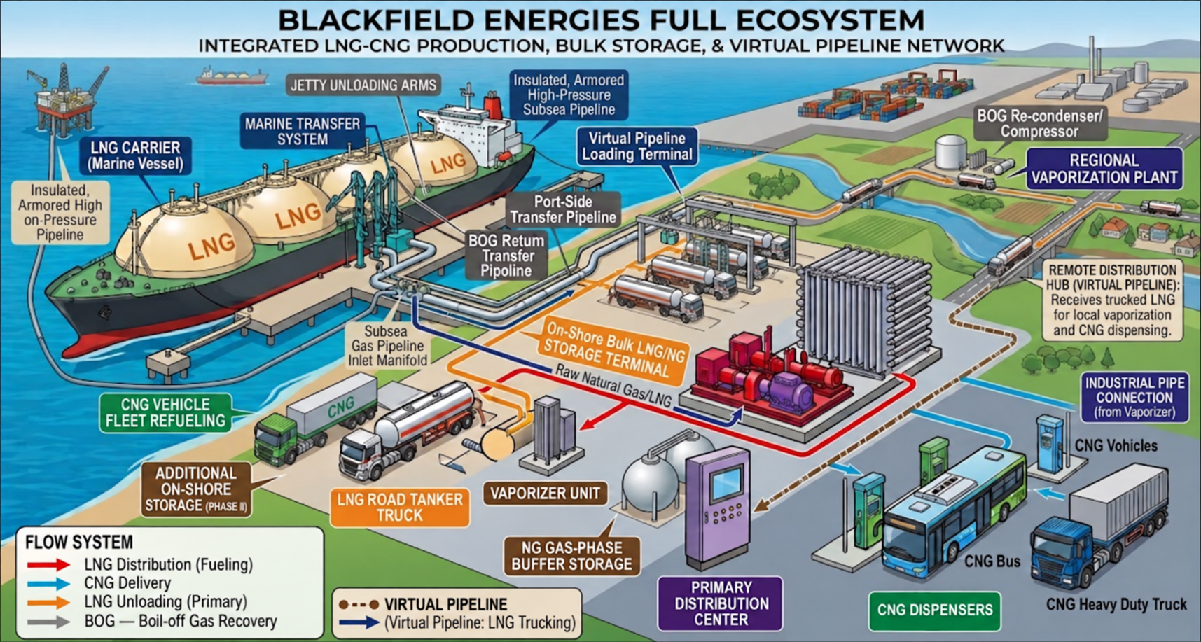
Marine supply → bulk storage → tanker loading → remote receiving hub. The road segment represents logistics, not an LNG pipeline across the landscape.
LNG supply → vaporization → gaseous natural gas → industrial connection. The line distinguishes liquid supply from the downstream gas service.
Vaporized / conditioned gas → compression and buffer storage → vehicle dispensing. This is an illustrative process pathway, not a guarantee of throughput or refuelling time.
The storage-side loop identifies a recovery-management function. Its actual destination, equipment and control philosophy must be established during detailed engineering.
This is our gas-supply concept, subject to detailed engineering. It shows how facilities could connect; it does not represent assets we own or operate, approved projects or committed construction.
Before approving a project, we require confirmation of supply, gas composition, pressure and temperature, equipment duties, utilities, layout, hazards and approvals. This concept does not include a defined liquefaction plant or subsea LNG-transfer design.
Technical references: EIA · LNG · AFDC · CNG
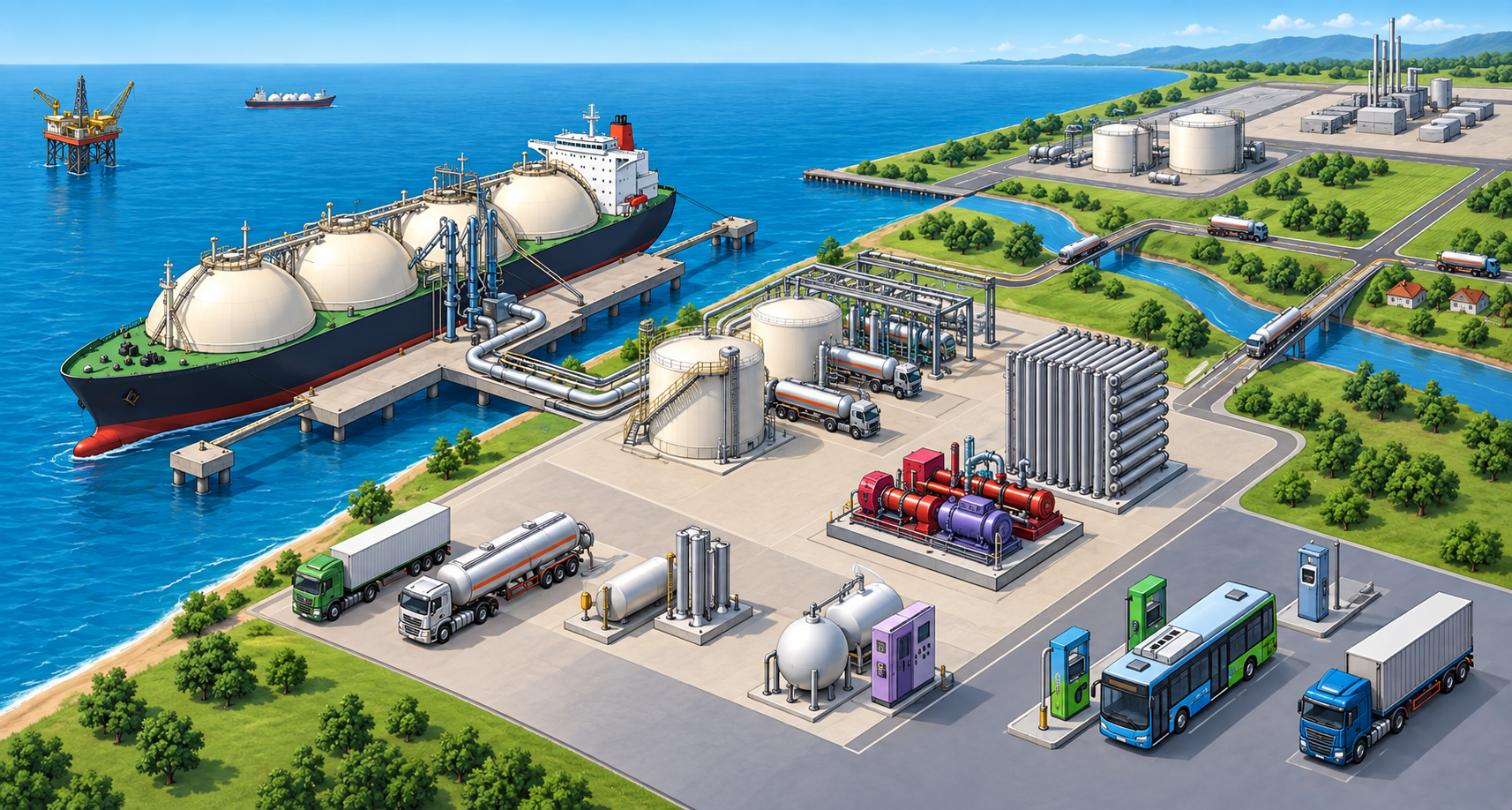
We retain the original illustration for context. Use our explanations alongside it; the image is a concept reference, not a verified engineering design.
I would like to discuss gas supply, delivery routes and receiving requirements for my project.
I would like to discuss a CNG station, equipment selection and site requirements.
I would like to discuss a fleet project, fuel demand and refuelling arrangements.